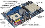
Motherboard is the main circuit board of a microcomputer. The motherboard contains the connectors for attaching additional boards. Typically, the motherboard contains the CPU, BIOS, memory, mass storage interfaces, serial and parallel ports, expansion slots, and all the controllers required to control standard peripheral devices, such as the display screen, keyboard, and disk drive. Collectively, all these chips that reside on the motherboard are known as the motherboard’s chipset.
If the processor is the brain and the RAM is the memory, then the motherboard is the backbone of the computer.
On most PCs, it is possible to add memory chips directly to the motherboard. You may also be able to upgrade to a faster PC by replacing the CPU chip. To add additional core features, you may need to replace the motherboard entirely. Motherboard is sometimes abbreviated as mobo.

Components of a motherboard
Today’s motherboards come with a whole host of features that you used to have to buy separately. Many motherboards now come with onboard sound, video, networking and USB interfaces for eliminating the need for a separate sound card, video card, network interface card and USB ports. You’ll probably find several differ types of slots on you board. It is important to know what these are for, as the number of them on your motherboard will affect the number of hard disks, memory chips, graphics cards, optical cards, modems, network cards, sound cards etc you can add to your system.
Expansion slot and sockets
It is an opening in a computer where a circuit board can be inserted to add new capabilities to the computer. Nearly all personal computers except portables contain expansion slots for adding more memory, graphics capabilities, and support for special devices. The boards inserted into the expansion slots are called expansion boards, adapters, expansion cards, cards.
Expansion slots for older PCs come in two basic sizes: half- and full-size. Half-size slots are also called 8-bit slots because they can transfer 8 bits at a time. Full-size slots are sometimes called 16-bit slots. In addition, modern PCs include PCI slots for expansion boards that connect directly to the PCI bus.
Expansion board
A printed circuit board that you can insert into a computer to give it added capabilities. For example, all of the following are expansion boards:
- video adapters;
- graphics accelerators;
- sound cards;
- Accelerator boards;
- Internal modems.
Expansion boards for PCs can be half-size (also half-length) or full-size (also full-length). Most PCs have slots for each type of board. A half-size board is sometimes called an 8-bit board because it can transmit only 8 bits at a time. A full-size board is called a 16-bit board. In addition, some expansion boards are designed to operate with a local bus, such as PCI.
CPU socket
The earlier processors are PGA type that contains a set of pins at the bottom of processor. To attach those processors, a motherboard must contain the processor socket of the same pin set. This type of sockets are often called ZIF socket as they do not need any force to insert them into the processor socket. Now a days the processor manufacturers are making pin-less processors. They use contact points instead if the pins. In this case motherboard must be different then the earlier one. Make sure that the socket type is right for the processor you have chosen and the case you have chosen.


DIMM slot

The earlier PCs were design for SIMM memory module. As technology gets higher the SIMM are altered by DIMM and in the last few years the DIMMs have changed in several times by bus speed, architecture, and physical structure. At present you will find SDRAM, DDR-SDRAM, DDR2-SDRAM in the market. They need different type of slots for attaching them with the motherboard. Some motherboard comes with multiple memory type supporting slots. You have to consider the memory slots for choicing the motherboard. Two slots are good but four slots are better.
AGP slot

This is for the graphics card; you only need one AGP slot. Now a days, the AGP is integrated with the motherboard. The graphic quality of display is also good. But if you plan for editing graphics and video or creating animations or playing game, you must buy a motherboard with spare AGP slot.
PCI slot

The PCIs are more generalized slots for expanding the capability of computer by attaching different circuit boards with them. For example, to get better performance you may install sound card for high quality sound output, gigabit Ethernet card, modem, internal TV card for surfing TV channels or you may add some other facility through the PCI slots that is not come with general motherboard. The PCI comes with different flavors. The original PCI is 64 bit wide but they are often used as 32 bit. Now a days the PCIs comes as PCI-X, PCI-Express 1X, PCI-Express 16X, PCI-Express 8X or simply PCI. The AGP itself a PCI slot with 8X capability.
IDE / SATA Slot
Abbreviation of either Integrated Drive Electronics. An IDE interface is an interface for mass storage devices, in which the controller is integrated into the disk or CD-ROM drive. Each motherboard contains some slots for attaching disk drives. The earlier motherboards come with at least two IDE slots. Now the IDE hard disks are going to be replaced by SATA hard disk as IDEs are slower storage device. Recent motherboard contains a single IDE slot and two to eight SATA slots .


Connectors
Motherboard contains some connectors for front panel use and expandability. For example, connectors for power & reset button, power lead, HDD status lead, optional front panel USB, Headphone & Microphone, internal audio speaker etc.
Interfaces
A boundary across which two independent systems meet and act on or communicate with each other. In computer technology, there are several types of interfaces.
- User interface – the keyboard, mouse, menus of a computer system. The user interface allows the user to communicate with the operating system.
- Software interface – the languages and codes that the applications use to communicate with each other and with the hardware.
- Hardware interface – the wires, plugs and sockets that hardware devices use to communicate with each other.
In general there are three types of Hardware Interface-
1. Special-purpose: The keyboard, sound card, mouse, etc. connectors represent the special-purpose interfaces. They cannot be used for any other device.
2. Multi-purpose: The parallel port (printer port), serial port, universal serial bus (USB), and IEEE 1394 FireWire represent multi-purpose interfaces since they can be used for various peripheral devices, including data storage devices.
3. General-purpose interfaces: The slots on the motherboard, such as PCI and ISA slots, can be used to connect various devices (via the plug-in cards) and represent truly general-purpose interfaces.
A basic definition of an interface is a hardware and / or software data transmission regulator that controls data exchange between the PC and other devices, including such data storage devices as hard disk drives, floppy drives, tape drives, CD drives, DVD drives, etc. The interface is supported by the electronics of the data transfer controller and the drive electronics. There are standards adopted for the interface protocols allowing connection of any standard peripheral device.
Some of the interface commonly found with recent PCs are discussed here shortly.
Parallel

Set up is easy, external and slow.
The parallel interface/port was originally created for communicating with the printer and thus is called a “printer port”. A PC may have at most 3 parallel ports, which are named LPT1, LPT2, and LPT3. A parallel port (printer port) female connector has 25 pins and looks like this:
At least 8 wires are needed for parallel transfer of 8 bits, but the standard IBM-type printer port uses 17 wires for data transfer plus some more to ground the system. These extra wires are used in intense hand shaking between the PC and the printer.
The computer puts 8 data bits on the 8 data lines and sends (on a separate line) a so-called strobe signal to the printer to inform it that 8 bits are ready to be transmitted. The printer reads the strobe signal and 8 bits and sends an acknowledgement signal on another wire back to the computer. In this way, the PC printer port does not send data to the printer faster than the printer can accept it. This data is not in any way synchronized by the clock signal and goes as fast as it can. There are five status wires that allow the printer to let the computer know when it is busy processing the data, or is out of paper or experiences a paper jam, etc. Four control wires allow the computer to command the printer to reset itself, to skip the page, etc. This ‘standard’ parallel port interface can sustain data rates up to 0.15 MB/s, which is faster than the serial port can reliably operate. To connect a parallel port to the printer one has to use a special 25-pin to 36-pin cable. This ‘standard’ parallel port is currently described in the IEEE (Institute of Electrical and Electronic Engineers) 1284 standard as a compatibility mode. There are four more newly created modes, which enhances parallel port performance.
One of the new modes is called a nibble-mode reverse operation, and another is the byte-reverse operation. Both of them represent modifications towards the bi-directional parallel port. The two other modes – the newest – are the EPP (Enhanced Parallel Port) and ECP (Extended Capability Port), which allow much faster data transfer rates and are widely used in parallel port storage devices such as Zip drives, hard drives, CD-ROM drives, etc.
In EPP design, five more CPU addresses were added to the initial 3 addresses to allow the CPU to transfer data in just one command rather than being involved in various steps of the PC- Printer handshaking. This, along with multiple bytes transfer, available for some EPP hardware designs, improved data transfer rates to almost 2 MB/s – about 10 times faster than in the standard ‘compatibility’ mode. EPP design also allowed block transfer of data and intermixing of data directions (from and to the computer) with no additional delays, which made it suitable for such peripherals as the Zip drive and others.
The ECP interface was meant for even higher data transfer rates than EPP. It utilizes data compression using the RLE (Run Length Encoding) protocol, which is most useful for compressing long sequences of repeated numbers. For example, if the sequence includes 105 zeros, it will be compressed by transmitting the following statement: “here come 105 zeros” instead of sending them all one by one.
A relatively loose handshaking protocol, along with the DMA (direct memory access), made possible even higher data transfer rates in one direction. To reverse the direction of data transfer, ECP needs several time-consuming steps. This makes the ECP interface less suitable for the external storage devices which often intermix the directions of the data transfer (reading and writing).
Using one port for more than one device used to be achieved via use of mechanical and electrical switch boxes.
Nowadays, the stackable port devices are used which have two parallel port connections: one “in” and one “out”. You may now plug a CD-ROM drive to the parallel port of your PC and attach the printer to the “printer” connector on the CD-ROM.
The device should be intelligent enough to figure out whether the command from the PC is addressed to the CD-ROM or the printer. Since this architecture is somewhat manufacturer dependent, it is hard to say in advance how many devices it is possible to connect in parallel. Sometime, reversing the order of connections will cause both devices to stop working. If you are lucky, several devices can be connected like this to the same parallel port of the PC.
Serial Interface:
If you send bits one at a time, you are using serial communication. If you send one extra bit for each 8 bits to make sure your data got there intact, it is called a parity bit. Bit parity can be odd or even. It is even, if you assign 0 to the parity bit when the sum of the 8 bits is a even number. In this case, you assign 1 to the parity bit when the sum is an odd number. The parity is odd, if the logics are reversed. After the byte has arrived, the system will sum 8 bits and check if it matches the even-or-oddness predicted by the parity bit.

Two common connector type are used for serial communication: the 9-pin connector DB9 and (less often) 25-pin DB25 connector, which is essentially the same. A serial port male connector looks like this:
The heart of the serial communication technology is the UART (Universal Asynchronous Receiver/Transmitter), which converts parallel streams of data into a single sequence. As soon as the CPU sends the bits to the UART, it is free for another job, and the UART will convert the data into a single sequence and send the bits one at a time over the serial cable using the internal clock to define the time interval for the next bit to be sent. The UART will also send the start bit, the stop bit, and the parity bit (if necessary).
Modern PCs can exchange data over the serial port at rates up to 115 KB/s, but this will translate into a maximum data rate of about only 11.5 KB/s without parity and 10.5 KB/s with parity due to the serial communication protocol overhead.
USB
Set up is very easy. Good performer. Hot swappable. Requires Windows 98 and higher.
USB interface is designed for easy, hassle-free, and relatively inexpensive low- and medium-speed applications. At the low end, USB can sustain a rate of less then 0.2 MB/s; in its fastest mode USB is capable of about 1.5 MB/s. USB can support isochronous data transfer mode, but the bandwidth will be much lower that for, for example, IEEE 1394 Firewire.
Windows 98 supports USB and there was a limited support for USB in Windows 95.
USB is still a serial-type interface and sends bits one after another…

USB makes adding peripheral devices very easy and is quickly replacing different kinds of serial and parallel port connectors with one standardized plug and port combination. One can now connect a USB-capable mouse, keyboard, digital joystick, a scanner, a set of digital speakers, a digital camera or a PC telephone to the computer.
In theory, a USB interface can support up to 127 individual USB peripherals at one time. The practical maximum number of devices is less since some of them reserve USB bandwidth. Additional PCI-based USB cards provide an independent USB bus so that even more peripheral devices can be connected.
For practical connection of multiple devices to the host (root), special hubs are required. Hubs notify the host when nodes (devices) attach or detach from the hub to provide the real-time reconfiguration of the system and device identification. Hubs can have up to seven connectors to nodes or other hubs. They could be self-powered or powered by the host. The next figure shows the topology of USB.
IEEE 1394 FireWire
Set up is easy. Excellent performer. Costly. Requires Windows 98 and higher.
The IEEE 1394 standard for the High Performance Serial Bus, also called Firewire, is a serial data transfer protocol and interconnection system. The main feature of the Firewire that assures its adoption for the digital video and audio (A/V) consumer application is its low cost. Fire wire interface is capable of supporting various high-end digital A/V applications, such as consumer A/V device control and signal routing, Digital Video (DV) editing, home networking, and more than 32 channels of digital mixing. Gone are those days of expensive video capture cards. Firewire allows for video capture from both newer DV camcorders with Firewire ports and older analog equipment using A/V to Firewire converters.
The first commercial products implementing Firewire technology were Sony’s DCR-VX700 and DCR-VX1000 digital video camcorders, introduced in 1995. Nowadays, growing variety of electronic products rely on the Firewire technology.
The advantages of the Firewire interface are summed bellow:
- High data transfer rate – up to 50 MB/s (400 Mbps), which is about 30 times faster than USB.
- Supports up to 63 devices (16 – daisy chained) with cable length up to about 4.5 m (14 feet).
- Hot-pluggable (like USB). No need to turn of your device to connect or disconnect, and you don’t need to reboot your PC. Also, Firewire is a plug-and-play bus.
- Firewire cables are very easy to connect (Like USB).

IEEE1394 Firewire interface standard is a serial interface which is relatively inexpensive, easy to use, and supports high data rate. Firewire allows easy data exchange between such devices as computers, camcorders, TV sets, speakers, and other consumer electronic devices.
Firewire was originally developed to replace fast but complex SCSI and offers bi-directional isochronous data transfer. Like USB, Firewire provides ‘plug and Play’ and ‘hot Plug In’ capabilities – allows to connect or disconnect devices without powering down and restarting the system. The list of devices supporting IEEE1394 is growing since it also enables transmitting audio, video, and control signals via the same cable. Since the power line is a part of the cable, power can be supplied directly to the low-power devices (mice, keyboard, etc.).
IEEE 1394 Basic Architecture
The Firewire cable bus is a ‘non-cyclic network with finite branches”, consisting of bus bridges and cable devices (nodes). Non-cyclic means that one can’t plug devices together to create a loop. Up to 16 cable hops are allowed between nodes, thus the term finite branches. 6-bit addressing allows up to 63 nodes to be connected to a single bus bridge. Thus, 63 connected devices is a limit for a conventional IEEE 1394 card in a PC.
Each node usually has three connectors, and up to 16 nodes can be connected in a ‘Daisy chain” through the connectors with standard cables up to 4.5 m long for a total of 72 m. Special high-quality ‘fatter’ cables allow longer interconnections. Additional devices can be added in a leaf-node configuration (shown in the next figure). Physical addresses are automatically assigned to the devices on bridge power up (bus reset) and when a new node is added or removed from the system. Hot plugging of the devices is fully supported. No device ID switches are required.
USB vs. IEEE 1394 “FireWire”
They are both serial type interfaces and transmit data one bit at a time. They are meant to be used with various peripherals ranging from a mouse to the speakers, DVD players or even a hard disk drive. Both interfaces are capable of supporting multiple devices and enable ‘communication’ between different peripherals without involving the host. Also, both USB and IEEE 1394 cables contain a power wires as well, which is enough for such devices as a mouse or a keyboard to function properly.
On the other hand, these two interfaces were designed for different data transfer ranges and for different cost needs. The Firewire IEEE 1394 interface is meant for high bandwidth and can be more then 30 times faster than USB. In the near future, Firewire may become even faster. At the same time, IEEE 1394 interface is considerably more expensive than USB.
USB and 1394 technologies are easy to use and compliment each other in terms of performance and cost and give a choice between high performance and high cost. The comparison of USB with Firewire is shown in the following table:
| Description | IEEE 1394 Firewire | USB |
| Maximum number of connected devices | 63 | 127 |
| Hot-swap? | Yes | Yes |
| Plug-and-Play? | Yes | Yes |
| Cable length between devices | 4.5 m | 5 m |
| Data transfer rate (MB/s) | 12.5/25/50 | 1.5 |
| PC / Mac | Yes / Yes | Yes / iMac only |
| Embedded power line | Yes | Yes |
| Peripheral devices | D-Camcorders, D-Cameras, Set-Top Boxes, HDTV, DVD-ROM, RAM, Hard Disk drives, Printers, Scanners | Keyboards, Mice, PC Monitors, Joysticks, DVD-ROM, RAM, Low-resolution D-Cameras, Low-speed CD-ROM, RW, Modems, Printers, Scanners |
| Relative cost | Higher | Lower |
- SCSI: Set up is even more difficult than for IDE. Best performer. Best when multiple devices are used. Generally needs a separate SCSI card.
- PC Card: Set up is easy. Good performance. For notebook use only.
GUI
Abbreviated GUI (pronounced GOO-ee). A program interface that takes advantage of the computer’s graphics capabilities to make the program easier to use. Well-designed graphical user interfaces can free the user from learning complex command languages. On the other hand, many users find that they work more effectively with a command-driven interface, especially if they already know the command language.
Graphical user interfaces, such as Microsoft Windows and the one used by the Apple Macintosh, feature the following basic components:
Pointer: A symbol that appears on the display screen and that you move to select objects and commands. Usually, the pointer appears as a small angled arrow. Text -processing applications, however, use an I-beam pointer that is shaped like a capital I.
pointing device: A device, such as a mouse or trackball that enables you to select objects on the display screen.
Icons: Small pictures that represent commands, files, or windows. By moving the pointer to the icon and pressing a mouse button, you can execute a command or convert the icon into a window. You can also move the icons around the display screen as if they were real objects on your desk.
desktop : The area on the display screen where icons are grouped is often referred to as the desktop because the icons are intended to represent real objects on a real desktop.
windows: You can divide the screen into different areas. In each window, you can run a different program or display a different file. You can move windows around the display screen, and change their shape and size at will.
menus : Most graphical user interfaces let you execute commands by selecting a choice from a menu.
The first graphical user interface was designed by Xerox Corporation’s Palo Alto Research Center in the 1970s, but it was not until the 1980s and the emergence of the Apple Macintosh that graphical user interfaces became popular. One reason for their slow acceptance was the fact that they require considerable CPU power and a high-quality monitor, which until recently were prohibitively expensive.
In addition to their visual components, graphical user interfaces also make it easier to move data from one application to another. A true GUI includes standard formats for representing text and graphics. Because the formats are well-defined, different programs that run under a common GUI can share data. This makes it possible, for example, to copy a graph created by a spreadsheet program into a document created by a word processor.
Many DOS programs include some features of GUIs, such as menus, but are not graphics based. Such interfaces are sometimes called graphical character-based user interfaces to distinguish them from true GUIs.
How to choice proper IDE/SCSI interface
Before choosing the storage unit of your PC or server you should go through the following description.
What is the hard drive?
Magnetic Hard Drive (HDD) is the direct access data storage device which is using local magnetizations of the hard magnetic disks to store bits of information.
What is the price range I should be looking for?
The price of the HDD storage was falling rapidly thanks to tough competition among the manufacturers and technological advances. It is still changing on the monthly basis. As a rule, you pay less for IDE drive than for SCSI drive, for lower rpm then for higher rpm, for internal drive then for the external drive. You definitely pay more for just released new drive. Since, there are various available on-line sites comparing prices, we advice you to shop around for the best deal…
What interface should I chose: IDE, uDMA, ATA-33, ATA-66, SCSI, USB, Parallel, etc.?
First of all, there are two major types of the interfaces applicable to the hard drives: IDE and SCSI. IDE stands for integrated drive electronics, SCSI stands for Small Computer System Interface. IDE is also called ultra DMA (direct memory access), ATA-3, 33, 66, or 100 (data transfer rate of up to 16 MB/sec, 33 MB/sec, 66 MB/s, and 100 MB/s). There are two major difference from the user’s point of view: data transfer rate and a possible number of drives used simultaneously.
If your requirements for data transfer rate are low to moderate, which is common for typical users of word processors, spreadsheets, graphic applications, small to medium size database, email programs, and for Internet surfing, IDE drive will be most satisfactory choice. Low-end (low-throughput) ATA-3 enhanced IDE drives are very inexpensive nowadays (thanks to integrated drive electronics (IDE) technology and competition) and provide up to 16 MB/sec data transfer rates. More advanced IDE drives, called ultra DMA or ATA-33 or ATA-66 drives, provide from up to 33 MB/sec to 66 MB/sec data transfer rates which rivals more expensive SCSI drives.
If you are a multimedia professional, graphic designer, network administrator, or software developer, or want to get maximum performance out of multiple hard drives, you may need to buy SCSI hard drives. Another reason for using SCSI is the need for the external hard disk drive. Next table summarizes your choices and possible conclusions:
| Type | Data rate (MBps) | Applications | Price (relative) | Pros / Cons |
| IDE drives (ultra DMA or enhanced DMA) |
up to 16 (enhances DMA) up to 100 (ultra DMA) |
Text processing, spreadsheets, medium intensity graphic editing, medium size databases, email and internet access. | low to medium | Low cost, simplicity of installation, relatively high performance / limited expandability, pure multitasking, lower data rate |
| SCSI | 40 to 80 | Multimedia, graphic design, network administration, software development, large databases, multiple hard drives (more than 3), external hard drive. | medium to high (extra $100 to $400 for a comparable drive) | extremely high data rates, excellent expandability (up to 7 to 15 drives, maximum performance out of multiple drives / higher cost, need for special card, more complex installation and configuration |
USB and parallel-port interfaces are used for the external drives, which are, in general, slower and also more expensive. Chose USB over Parallel port, when possible.
What are the main performance parameters to look for?
Depending of what yours applications are. For example, for servers or real-time applications (video, audio, etc.), the data transfer rate (DTR) may be the most important parameter. The data transfer rate is, in general, a function of the drive’s RPM (i.e., 3600, 4200, 5400, 7200, 10000, or 15000) for a given type of drive interface. Look for higher rpm values or read data rate values directly from the drive’s cover or from the provided datasheet.
Quite often, people pay too much attention to the Average Seek Time or Access Time. But, this parameters are the measures of the drive’s internal data transfer rate rather than the external (between the drive and the host PC). In fact, these parameters only represent the time needed for the magnetic head to be positioned over the needed bit of data. We will encourage you to pay more attention to the DTR values in the drive’s specification, since they correspond to the real drive throughput and not to the internal data transfer rate.
Another important parameter is the total drive’s capacity. It is important for all kinds of drives, since the cost of GB is falling continuously. For the laptop (mobile) computers, for example, the data rate could be much less important than capacity, since laptops are rarely used for speed-hungry applications such as video-editing, heavy graphics, large databases, etc.
A head-to-head comparison of the drive’s performance is also a good way to select a favorite.
What are other parameters I should consider before buying the drive?
Nowadays, manufacturer’s warranty is the same for all drive’s manufacturers – 3 years. A different question is – will there be anyone left to honor this warranty one or two years later? We will risk to predict, that IBM and Seagate will still be around, while the future success of, say, WDC (Western Digital Corporation) is questionable.
Drive’s reliability figures, such as MTBF (mean time before failure) is something to look at, but this also should not differ too much from one drive to another.
A customer support and easiness of the drive’s installation process vary significantly from one manufacturer to another.
How many drives I can install on my computer?
IDE controllers are limited to 4 devices on a chain (2 on older ones).
SCSI controllers are designed for multitasking and can support from 7 to 15 devices.
In particular, SCSI-1, Fast SCSI-2, Ultra SCSI-3 (8-bit) and Ultra-2 SCSI support 7 devices on a chain, while SCSI-2, Wide SCSI-2, Fast Wide SCSI-2, Ultra SCSI-3 (16-bit), and Wide Ultra-2 SCSI support up to 15 devices.
Therefore, if you have IDE controller and need more HDD storage, you may go with fewer but larger drives. SCSI controller will allow you to have multiple smaller drives thus increasing system reliability (and complexity).
Is there any size limitation for the drive?
Unfortunately, yes. Earlier computer used much smaller hard drives then today, and the BIOS designers did not anticipate future multi-gigabyte drives.
If your computer was built in 1997 or earlier, it’s BIOS (Basic Input/Output System) will not, most likely, support drives larger than 8.4 GB (or even less then that). When the system accesses the disk (reads or writes data), the BIOS uses a software interrupt 13h. This interrupt was initially assigned 24 bits of addressing, which only allows the system to access 8.4GB on a disk drive. Since then, the extensions for interrupt 13 were defined allowing 64 bits of addressing, which is equal to upper limit of 9.4 Tera (1012) Gigabytes, which effectively eliminates the problem. Most systems newer than 1998 should properly address interrupt 13h. Systems without the support can be modified to use drives greater than 8.4 GB.
If your current system has this problem, it could be addressed as following:
- Contact your PC or BIOS manufacture to obtain newer version of BIOS that supports the interrupt 13 extensions.
- A majority of modern PCs have a so-called flash BIOS with all information recorded on an updateable flash memory chip.
- Using software utilities to modify your BIOS.
Another limitation is file system related and could be solved by upgrading your operating system. Find more here (section “File System”). If you have Windows 98, you have no problem with your file system limitations since it is FAT32. If you have Windows 95, you may check if it supports FAT32 file system:
go to START–> SETTINGS –> CONTROL PANEL –> SYSTEM icon –> GENERAL –> if SYSTEMS PROPERTIES shows:
4.00.950b -This version supports the extended file system (FAT32.) and you have no problem with the file system.
*4.00.950 or 4.00.950a -This version only supports FAT16 and you have 2.1 GB limitation. This means that if you use larger drive, you will be forced to partition it with FDISK program to many logical disks of not larger than 2.1 GB.
Can I use the same drive for the desktop and for the laptop computers?
If you laptop has the parallel, SCSI, or USB port, you may always connect it to the external drive of the same type.Usually, mobile computers use the small from-factor hard drives similar (in general) to those used by the desktops, but they are mounted inside a custom holder that slips into the laptop’s case and locks in place. Therefore, when buying the drive for the laptop, make sure to check its compatibility with your type of computer.
The IDE drives used in the laptop could be used for the desktop computers with the help of a cable adapter. There could be problems with fixing the smaller drive inside a larger bay of the desktop.
Ports

Port is an interface on a computer to which you can connect a device. Personal computers have various types of ports. There are several ports for connecting disk drives, display screens, and keyboards. Personal computers have ports for connecting modems, printers, mice, and other peripheral devices.
Hardware port
A hardware port is an electrically wired outlet on a piece of equipment into which a plug or cable connects. These hardware ports have different physical shapes such as male, female, round, rectangular, square, oblong, etc. There is some standardization to physical properties and function. For instance, most computers have a keyboard port (currently round, or telephone type), into which the keyboard is connected.
Hardware ports can almost always be divided into two groups:
- Serial ports send and receive one bit at a time via a single wire pair (Ground and +/-).
- Parallel ports send multiple bits at the same time over several sets of wires.
The system bus that holds circuit cards for a computer “Mother Board” is a form of parallel port. Note that light fiber, microwave, and other technologies (i.e. quantum) may have special cases.
Almost all personal computers come with a serial RS-232C port or RS-422 port for connecting a modem or mouse and a parallel port for connecting a printer. On PCs, the parallel port is a Centronics interface that uses a 25-pin connector. SCSI (Small Computer System Interface) ports support higher transmission speeds than do conventional ports and enable you to attach up to seven devices to the same port.
Software / Network port
The TCP and UDP protocols use ports to map incoming data to a particular process running on a computer.
One can imagine computers having thousands of numbered hardware ports, each with wires sticking out of them. In this imagined scenario, applications could communicate as follows: Application A listens for network traffic arriving on, say, port 90. Application B knows that Application A is always listening on port 90, so it sends some data down the corresponding wire. The number of concurrent listening applications is limited by the number of wires there are sticking out of the computer. This is the illusion created by network ports. Of course, in reality, there is (usually) only one hardware port (the network socket). The illusion is created by sending data to this single hardware port, but including in the transmission the number of the network port. Thus, an application can choose to see only traffic sent to its port.
Whether or not network ports are used depends on the transport layer. Both UDP and TCP use ports.
A port may send/receive data one direction at a time (simplex) or simultaneously in both directions (duplex). Software network ports may also connect internal programs on a single computer system. For example, port 80 is used for HTTP traffic.
In TCP and UDP the combination of a port and a network address (IP-number) is called a socket: e.g. the TCP and UDP port numbers.
DTE and DCE
The terms DTE and DCE are very common in the data communications market. DTE is short for Data Terminal Equipment and DCE stands for Data Communications Equipment. But what do they really mean? As the full DTE name indicates this is a piece of device that ends a communication line, whereas the DCE provides a path for communication.
Different Type of Ports
According to earlier discussion two type of hardware ports are serial and parallel
In computing, a serial port consists of an interface on a computer system through which information transfers in or out one bit at a time (contrast parallel port). Throughout most of the history of personal computers, data transfer using serial ports took place using the RS-232 standard over simple cables connecting the computer to a device such as a terminal or a modem. Mice, keyboards, and other devices also connected to their hosts in this way.


While such interfaces as Ethernet networks, FireWire, and USB all send data as a serial stream, the term “serial port” usually identifies hardware intended to interface with a modem or with a similar communication device.
RS-232C
Short for recommended standard-232C, a standard interface approved by the Electronic Industries Alliance (EIA) for connecting serial devices. In 1987, the EIA released a new version of the standard and changed the name to EIA-232-D. And in 1991, the EIA teamed up with Telecommunications Industry association (TIA) and issued a new version of the standard called EIA/TIA-232-E. Many people, however, still refer to the standard as RS-232C, or just RS-232.
Almost all modems conform to the EIA-232 standard and most personal computers have an EIA-232 port for connecting a modem or other device. In addition to modems, many display screens, mice, and serial printers are designed to connect to a EIA-232 port. In EIA-232 parlance, the device that connects to the interface is called a Data Communications Equipment (DCE) and the device to which it connects (e.g., the computer) is called a Data Terminal Equipment (DTE).
The EIA-232 standard supports two types of connectors — a 25-pin D-type connector (DB-25) and a 9-pin D-type connector (DB-9). The type of serial communications used by PCs requires only 9 pins so either type of connector will work equally well.
Although EIA-232 is still the most common standard for serial communication, the EIA has recently defined successors to EIA-232 called RS-422 and RS-423. The new standards are backward compatible so that RS-232 devices can connect to an RS-422 port.
RS-422 and RS-423
Standard interfaces approved by the Electronic Industries Alliance (EIA) for connecting serial devices. The RS-422 and RS-423 standards are designed to replace the older RS-232 standard because they support higher data rates and greater immunity to electrical interference. All Apple Macintosh computers contain an RS-422 port that can also be used for RS-232C communication.
RS-422 supports multi point connections whereas RS-423 supports only point-to-point.

PS/2 port or Mini DIN
A type of serial port developed by IBM for connecting a mouse or keyboard to a PC. The PS/2 port supports a mini DIN plug containing just 6 pins. Most PCs have a PS/2 port so that the serial port can be used by another device, such as a modem. The PS/2 port is often called the mouse port.
DIN is short for Deutsches Insitut für Normung eV, the standards -setting organization for Germany. A DIN connector is a connector that conforms to one of the many standards defined by DIN. DIN connectors are used widely in personal computers. For example, the keyboard connector for PCs is a DIN connector.

DIN connector
DIN 41612 connectors are used widely to connect network equipment, such as routers and switches.
USB
Short for Universal Serial Bus, an external bus standard that supports data transfer rates of 12 Mbps. A single USB port can be used to connect up to 127 peripheral devices, such as mice, modems, and keyboards. USB also supports Plug-and-Play installation and hot plugging.
Starting in 1996, a few computer manufacturers started including USB support in their new machines. It wasn’t until the release of the best-selling iMac in 1998 that USB became widespread. It is expected to completely replace serial and parallel ports.

USB 2.0
Also referred to as Hi-Speed USB, USB 2.0 is an external bus that supports data rates up to 480Mbps. USB 2.0 is an extension of USB 1.1. USB 2.0 is fully compatible with USB 1.1 and uses the same cables and connectors.
Hewlett-Packard, Intel, Lucent, Microsoft, NEC and Philips jointly led the initiative to develop a higher data transfer rate than the 1.1 specification to meet the bandwidth demands of developing technologies. The USB 2.0 specification was released in April 2000.
IEEE 1394


A very fast external bus standard that supports data transfer rates of up to 400Mbps (in 1394a) and 800Mbps (in 1394b). Products supporting the 1394 standard go under different names, depending on the company. Apple, which originally developed the technology, uses the trademarked name FireWire. Other companies use other names, such as i.link and Lynx, to describe their 1394 products.
A single 1394 port can be used to connect up 63 external devices. In addition to its high speed, 1394 also supports isochronous data — delivering data at a guaranteed rate. This makes it ideal for devices that need to transfer high levels of data in real-time, such as video devices.
Although extremely fast and flexible, 1394 is also expensive. Like USB, 1394 supports both Plug-and-Play and hot plugging, and also provides power to peripheral devices.
COM
In DOS systems, the name of a serial communications port. DOS supports four serial ports: COM1, COM2, COM3, and COM4. However, most software uses system interrupts to access the serial ports, and there are only two IRQ lines reserved. This means that the four COM ports share the same two IRQ lines. Typically, COM1 and COM3 use IRQ4, while COM2 and COM4 use IRQ3. So in general, if you have two devices, one of which is attached to COM1 and the other to COM3, you cannot use them simultaneously.
Parallel Port
A parallel interface for connecting an external device such as a printer. Most personal computers have both a parallel port and at least one serial port.

On PCs, the parallel port uses a 25-pin connector (type DB-25) and is used to connect printers, computers and other devices that need relatively high bandwidth. It is often called a Centronics interface after the company that designed the original standard for parallel communication between a computer and printer. (The modern parallel interface is based on a design by Epson.)

A newer type of parallel port, which supports the same connectors as the Centronics interface, is the EPP (Enhanced Parallel Port) or ECP (Extended Capabilities Port). Both of these parallel ports support bi-directional communication and transfer rates ten times as fast as the Centronics port.
Macintoshes have a SCSI port, which is parallel, but more flexible.
PCMCIA
Short for Personal Computer Memory Card International Association, and pronounced as separate letters, PCMCIA is an organization consisting of some 500 companies that has developed a standard for small, credit card-sized devices, called PC Cards. Originally designed for adding memory to portable computers, the PCMCIA standard has been expanded several times and is now suitable for many types of devices. There are in fact three types of PCMCIA cards. All three have the same rectangular size (85.6 by 54 millimeters), but different widths

Type I cards can be up to 3.3 mm thick, and are used primarily for adding additional ROM or RAM to a computer.
Type II cards can be up to 5.5 mm thick. These cards are often used for modem and fax modem cards.
Type III cards can be up to 10.5 mm thick, which is sufficiently large for portable disk drives.
As with the cards, PCMCIA slots also come in three sizes:
A Type I slot can hold one Type I card
A Type II slot can hold one Type II card or one Type I card
A Type III slot can hold one Type III card or any combination of two Type I or II cards.
In general, you can exchange PC Cards on the fly, without rebooting your computer. For example, you can slip in a fax modem card when you want to send a fax and then, when you’re done, replace the fax modem card with a memory card.
BIOS
BIOS is acronym for basic input/output system, the built-in software that determines what a computer can do without accessing programs from a disk. On PCs, the BIOS contains all the code required to control the keyboard, display screen, disk drives, serial communications, and a number of miscellaneous functions.
The BIOS is typically placed in a ROM chip that comes with the computer (it is often called a ROM BIOS). This ensures that the BIOS will always be available and will not be damaged by disk failures. It also makes it possible for a computer to boot itself. Because RAM is faster than ROM, though, many computer manufacturers design systems so that the BIOS is copied from ROM to RAM each time the computer is booted. This is known as shadowing[1].
Many modern PCs have a flash BIOS, which means that the BIOS has been recorded on a flash memory[2] chip, which can be updated if necessary.
The PC BIOS is fairly standardized, so all PCs are similar at this level (although there are different BIOS versions). Additional DOS functions are usually added through software modules. This means you can upgrade[3] to a newer version of DOS without changing the BIOS.
PC BIOSes that can handle Plug-and-Play (PnP) devices are known as PnP BIOSes, or PnP-aware BIOSes. These BIOSes are always implemented with flash memory rather than ROM.
PXE ROM
Short for Pre-Boot Execution Environment. Pronounced pixie, PXE is one of the components of Intel’s WfM[4] specification. It allows a workstation to boot from a server on a network prior to booting the operating system on the local hard drive. A PXE-enabled workstation connects its NIC to the LAN via a jumper, which keeps the workstation connected to the network even when the power is off. Because a network administrator does not have to physically visit the specific workstation and manually boot it, operating systems and other software, such as diagnostic programs, can be loaded onto the device from a server over the network.
PXE is a mandatory element of the WfM specification. To be considered compliant, the PXE must be supported by the computer’s BIOS and its NIC.
Power-on self-test
Abbreviated POST, a diagnostic testing sequence run by a computer’s BIOS as the computer’s power is initially turned on. The POST will determine if the computer’s RAM, disk drives, peripheral devices and other hardware components are properly working. The POST routine performs the following tests:
a. It checks systems for hardware error including configuration error.
b. It detects interrupt, I/O address or Base memory address conflicts. If any major error found during the POST routine then either an error code number or a series of beeps will tell the cause of error. [See Appendix-I on page-Error! Bookmark not defined. for beep codes of different BIOS’s]
If the diagnostic determines that everything is in working order, the computer will continue to boot.
Boot sequence
The order of drives that a system’s BIOS follow when looking for the operating system (OS) to boot after the computer has performed POST. For example, the BIOS may be instructed to first look to drive C (i.e., the hard disk) for the OS and then drive A (i.e., the floppy disk). If the OS is stored in drive C then the BIOS need look no further; however, if the BIOS does not find the OS in drive C then it will next look to drive A, and so on depending on the configuration of the boot sequence.
Users can change the order of the boot sequence through the CMOS[5] setup.
Motherboard Chipset

The chip set is very important to the modern PC and its performance. Many technologies meet on the motherboard and are “glued” together via these controllers, which we call the “chip set”.
When we speak about buses and motherboards, we are also speaking about chip sets. The chip sets are a bunch of intelligent controller chips, which are on any motherboard.
The term is often used to refer to the core functionality of a motherboard.
The controllers are closely tied to the CPU, in that they control the buses around the CPU. Without the chip sets, neither RAM nor I/O buses could function together with the CPU:
So Chipset is a number of integrated circuits designed to perform one or more related functions. For example, one chipset may provide the basic functions of a modem while another provides the CPU functions for a computer. Newer chipsets generally include functions provided by two or more older chipsets. In some cases, older chipsets that required two or more physical chips can be replaced with a chipset on one chip.
Some chipset suppliers and models:
There are several suppliers of chip sets for the motherboard:
- Intel
- SIS
- Opti
- Via
- ALi
Intel has until now been the leader in supplying chip sets to the Pentium motherboard. The 82450GX, 82440FX – Natoma, 82440LX, 82440BX, 82443EX PCI AGP Controller (PAC), 82371AB PCI-TO-ISA/IDE Xcelerator (PIIX4), VIA Apollo Pro, Apollo Pro+, VIA and S3, chip sets were of much higher quality, and within very few years they lead to several new generations of chip sets, each of them more powerful and offering great new features.
Controller:
A device that controls the transfer of data from a computer to a peripheral device and vice versa. For example, disk drives, display screens, keyboards, and printers all require controllers.
In personal computers, the controllers are often single chips. When you purchase a computer, it comes with all the necessary controllers for standard components, such as the display screen, keyboard, and disk drives. If you attach additional devices, however, you may need to insert new controllers that come on expansion boards.
Controllers must be designed to communicate with the computer’s expansion bus. There are three standard bus architectures for PCs — the AT bus, PCI (Peripheral Component Interconnect), and SCSI. When you purchase a controller, therefore, you must ensure that it conforms to the bus architecture that your computer uses.
AT
Short for advanced technology, the AT is an IBM PC model introduced in 1984. It includes an Intel 80286 microprocessor, a 1.2MB floppy drive, and an 84-key AT keyboard. Today, the term is used more generally to refer to any PC with an 80286 processor.
ATX
The modern-day shape and layout of PC motherboards. It improves on the previous standard, the Baby AT form factor, by rotating the orientation of the board 90 degrees. This allows for a more efficient design, with disk drive cable connectors nearer to the drive bays and the CPU closer to the power supply and cooling fan.
BUS
A collection of wires and electronic components through which data is transmitted from one part of a computer to another, even from one computer to another computer. You can think of a bus as a highway on which data travels within a computer. When used in reference to personal computers, the term bus usually refers to internal bus. This is a bus that connects all the internal computer components to the CPU and main memory. There’s also an expansion bus that enables expansion boards to access the CPU and memory.
All buses consist of two parts — an address bus and a data bus. The data bus transfers actual data whereas the address bus transfers information about where the data should go.

The size of a bus, known as its width, is important because it determines how much data can be transmitted at one time. For example, a 16-bit bus can transmit 16 bits of data, whereas a 32-bit bus can transmit 32 bits of data.
Every bus has a clock speed measured in MHz. A fast bus allows data to be transferred faster, which makes applications run faster. On PCs, the old ISA bus is being replaced by faster buses such as PCI.
Nearly all PCs made today include a local bus for data that requires especially fast transfer speeds, such as video data. The local bus is a high-speed pathway that connects directly to the processor.
Several different types of buses are used on Apple Macintosh computers. Older Macs use a bus called NuBus, but newer ones use PCI.
In networking, a bus is a central cable that connects all devices on a local-area network (LAN). It is also called the backbone[6].
Physical parts of Buses
Buses carry data and instruction. Sometimes buses are used to access some specific blocks of physical memory. In this case they may or may not carry any data or instruction. All the data line in a bus system do not carry same type of data. According to their function bus can be categorized as follows-
Data Bus
The data bus carries digital information. A data bus is usually a group of parallel wires connecting different parts of a circuit with each individual wire carrying a different logic signal. The data bus is connected to the inputs of several gates and to the outputs of several gates. In general, information may flow on the bus wires in both directions. This type of bus is referred to as a bidirectional data bus.
Control Bus
The physical connections that carry control information between the CPU and other devices within the computer. Whereas the data bus carries actual data that is being processed, the control bus carries signals that report the status of various devices. For example, one line of the bus is used to indicate whether the CPU is currently reading from or writing to main memory.
Address Bus
An address bus is a collection of wires connecting the CPU with main memory that is used to identify particular locations (addresses) in main memory. Address bus is a part of a computer bus. The width of the address bus (that is, the number of wires) determines how many unique memory locations can be addressed. For example, a 16-bit wide address bus (commonly used in the 8-bit processors of the 1970s and early 1980s) reaches across 2 to the power of 16 = 65,536 = 64K memory locations, whereas a 32-bit address bus (common in today’s PC processors) can address 4,294,967,296 = 4G locations.
Modern PCs and Macintoshes have as many as 36 address lines, which enables them theoretically to access 64 GB (gigabytes) of main memory. However, the actually amount of memory that can be accessed is usually much less than this theoretical limit due to chipset and motherboard limitations.
In most microcomputers the addressable elements are 8-bit bytes (so a “K” in that case is equal to a “KB”, i.e. a kilobyte), while there are also many examples of computers with larger “chunks” of data as their minimum physically addressable elements, notably mainframes, supercomputers, and some workstation CPUs.
CPU BUS
Internal Bus/ Internal Data Bus: A bus that operates only within the internal circuitry of the CPU, communicating among the internal caches of memory that are part of the CPU chip’s design. This bus is typically rather quick and is independent of the rest of the computer’s operations.
Contrast with external data bus. The bit width of internal and external data buses are not always equal.
Microprocessors communicate with its internal and external components through the bus, are mainly divided into two categories. They are discussed below-
Front-side Bus: Another name for the system bus. The bus that connects the CPU to main memory on the motherboard. I/O buses, which connect the CPU with the systems other components, branch off of the system bus. The system bus is also called the memory bus, local bus, or host bus.
Backside bus: A microprocessor bus that connects the CPU to a Level 2 cache. Typically, a backside bus runs at a faster clock speed than the frontside bus that connects the CPU to main memory. For example, the Pentium Pro microprocessor actually consists of two chips — one contains the CPU and the primary cache, and the second contains the secondary cache. A backside bus connects the two chips at the same clock rate as the CPU itself (at least 200 MHz). In contrast, the frontside bus runs at only a fraction of the CPU clock speed.
Expansion Bus
A collection of wires and protocols[7] that allows the expansion of a computer by inserting printed circuit boards (expansion boards). Traditionally, PCs have utilized an expansion bus called the ISA bus. In recent years, however, the ISA bus has become a bottleneck, so nearly all new PCs have a PCI bus for performance as well as an ISA bus for backward compatibility.
AT Bus
The expansion bus on the IBM PC/AT and compatible computers.
The AT bus, which runs at 8 megahertz and has a 16-bit data path, is the de facto standard for PCs. Because all IBM PCs (until the high-end PS/2 models) had an AT bus, it has been possible for manufacturers to produce expansion boards that will work with any PC.
The AT bus is sometimes referred to as the ISA bus, which stands for Industry Standard Architecture. However, ISA also includes the XT bus, which is an 8-bit version of the AT bus.
As processors have become more powerful, and applications more demanding, the AT bus has turned out to be the chief bottleneck in PCs. In response, IBM introduced the Micro Channel Architecture (MCA[8]) in 1987. A more successful alternative to the AT bus is the Extended Industry Standard Architecture (EISA ), a high-speed 32-bit bus architecture developed by a group of IBM’s competitors. Unlike MCA, EISA is backward compatible with the AT bus, so a computer equipped with an EISA bus can accept AT or EISA expansion boards.
While EISA has had limited success, its speeds are still insufficient for modern graphical applications. The most common solution to bypassing the AT-bus bottleneck is to include a local bus on the motherboard. A local bus communicates directly with the processor rather than using the standard computer bus. Currently, there are two competing standards for local buses: VESA local bus (VL-bus), promoted by the VESA standards group, and Peripheral Component Interconnect (PCI), designed and promoted by Intel.

ISA Bus

Short for Industry Standard Architecture bus, the bus architecture used in the IBM PC/XT and PC/AT. Pronounced as separate letters or as eye-sa. The AT version of the bus is called the AT bus and became a de facto industry standard. Starting in the early 90s, ISA began to be replaced by the PCI local bus architecture. Most computers made today include both an AT bus for slower devices and a PCI bus for devices that need better bus performance.
In 1993, Intel and Microsoft introduced a new version of the ISA specification called Plug and Play ISA. Plug and Play ISA enables the operating system to configure expansion boards automatically so that users do not need to fiddle with DIP switches[9] and jumpers[10].
Image: Dip Switch and Jumper.
EISA Bus
Acronym for Extended Industry Standard Architecture, a bus architecture designed for PCs using an Intel 80386, 80486, or Pentium microprocessor. EISA buses are 32 bits wide and support multiprocessing.
The EISA bus was designed by nine IBM competitors (sometimes called the Gang of Nine): AST Research, Compaq Computer, Epson, Hewlett-Packard, NEC, Olivetti, Tandy, WYSE, and Zenith Data Systems. They designed the architecture to compete with IBM’s own high-speed bus architecture called the Micro Channel architecture (MCA).
The principal difference between EISA and MCA is that EISA is backward compatible with the ISA bus (also called the AT bus), while MCA is not. This means that computers with an EISA bus can use new EISA expansion cards as well as old AT expansion cards. Computers with an MCA bus can use only MCA expansion cards.
EISA and MCA are not compatible with each other. This means that the type of bus in your computer determines which expansion cards you can install.
Neither EISA nor MCA has been very successful. Instead, a new technology called local bus (PCI) is being used in combination with the old ISA bus
Local Bus
A data bus that connects directly, or almost directly, to the microprocessor. Although local buses can support only a few devices, they provide very fast throughput[11]. Modern PCs include both a PCI local bus and a more general ISA expansion bus for devices that do not require such fast data throughput.
VL-bus
Short for VESA Local-Bus, a local bus architecture created by the Video Electronics Standards Association (VESA ). Although it was quite popular in PCs made in 1993 and 1994, it has been overshadowed by a competing local bus architecture called PCI.
PCI Bus
Short for Peripheral Component Interconnect, a local bus standard developed by Intel Corporation. Most modern PCs include a PCI bus in addition to a more general ISA expansion bus. PCI is also used on newer versions of the Macintosh computer.
PCI is a 64-bit bus, though it is usually implemented as a 32-bit bus. It can run at clock speeds of 33 or 66 MHz. At 32 bits and 33 MHz, it yields a throughput rate of 133 MBps.
Although it was developed by Intel, PCI is not tied to any particular family of microprocessors.
PCI-X Bus
Short for PCI extended, an enhanced PCI bus. PCI-X is backward-compatible with existing PCI cards. It improves upon the speed of PCI from 133 MBps to as much as 1 GBps.
PCI-X was designed jointly by IBM, HP and Compaq to increase performance of high bandwidth devices, such as Gigabit Ethernet and Fibre Channel, and processors that are part of a cluster.
PCI Express
An I/O interconnect bus standard (which includes a protocol and a layered architecture) that expands on and doubles the data transfer rates of original PCI. PCI Express is a two-way, serial connection that carries data in packets along two pairs of point-to-point data lanes, compared to the single parallel data bus of traditional PCI that routes data at a set rate. Initial bit rates for PCI Express reach 2.5Gb/s per lane direction, which equate to data transfer rates of approximately 200MB/s. PCI Express was developed so that high-speed interconnects such as 1394b, USB 2.0, InfiniBand and Gigabit Ethernet would have an I/O architecture suitable for their transfer high speeds.
PCI Express, also known as 3GIO (for third-generation Input/Output) is compatible with existing PCI systems.
NuBus
The expansion bus for versions of the Macintosh computers starting with the Macintosh II and ending with the Performa. Current Macs use the PCI bus.
SMBus
The System Management Bus (SMBus) is a two-wire interface through which simple power-related chips can communicate with rest of the system. It uses I2C as its backbone. With the SMBus, a device can provide manufacturer information, tell the system what its model or part number is, save its state for a suspend event, report different types of errors, accept control parameters and return its status.
I2C
Short for Inter-IC, a type of bus designed by Philips Semiconductors in the early 1980s, which is used to connect integrated circuits (ICs). I2C is a multi-master bus, which means that multiple chips can be connected to the same bus and each one can act as a master by initiating a data transfer. I2C is used in many devices, especially video devices such as computer monitors, televisions and VCRs.
VSB
Short for VME Subsystem Bus, an auxiliary bus used with a primary 32-bit bus called a VME (VersaModule Eurocard), made for commercial, industrial, and military uses. The VSB helps speed transfers between devices.
VME Bus
(VersaModule Eurocard bus) A 32-bit bus developed by Motorola, Signetics, Mostek and Thompson CSF. It is widely used in industrial, commercial and military applications with over 300 manufacturers of VMEbus products worldwide. VME64 is an expanded version that provides 64-bit data transfer and addressing.
External Bus
Another name for external data bus, A bus that connects a computer to peripheral devices. Two examples are the Universal Serial Bus (USB) and IEEE 1394. Contrast with internal data bus. The bit widths of internal and external data buses are not always equal.
USB
Short for Universal Serial Bus, an external bus standard that supports data transfer rates of 12 Mbps. A single USB port can be used to connect up to 127 peripheral devices, such as mice, modems, and keyboards. USB also supports Plug-and-Play installation and hot plugging.
Starting in 1996, a few computer manufacturers started including USB support in their new machines. It wasn’t until the release of the best-selling iMac in 1998 that USB became widespread. It is expected to completely replace serial and parallel ports.
USB 2.0
Also referred to as Hi-Speed USB, USB 2.0 is an external bus that supports data rates up to 480Mbps. USB 2.0 is an extension of USB 1.1. USB 2.0 is fully compatible with USB 1.1 and uses the same cables and connectors.
Hewlett-Packard, Intel, Lucent, Microsoft, NEC and Philips jointly led the initiative to develop a higher data transfer rate than the 1.1 specification to meet the bandwidth demands of developing technologies. The USB 2.0 specification was released in April 2000.
USB OTG
Short for USB On-The-Go, an extension of the USB 2.0 specification for connecting peripheral devices to each other. USB OTG products can communicate with each other without the need to be connected to a PC. For example, a digital camera can connect to a PDA, or a mobile phone can connect to a printer or a scanner, as long as all the devices are USB OTG-compatible. USB OTG grew from the increasing need for portable devices to be able to communicate with each other as the culture of technology moves away from a PC-centric world.
One of the important features of USB OTG is that the standard does not require a host PC in order for the devices to communicate. USB OTG devices, known as dual-role peripherals, can act as limited hosts or peripherals themselves depending on how the cables are connected to the devices, and they also can connect to a host PC.
IEEE 1394
A very fast external bus standard that supports data transfer rates of up to 400Mbps (in 1394a) and 800Mbps (in 1394b). Products supporting the 1394 standard go under different names, depending on the company. Apple, which originally developed the technology, uses the trademarked name FireWire. Other companies use other names, such as i.link and Lynx, to describe their 1394 products.
A single 1394 port can be used to connect up 63 external devices. In addition to its high speed, 1394 also supports isochronous[12] data — delivering data at a guaranteed rate. This makes it ideal for devices that need to transfer high levels of data in real-time, such as video devices.
Although extremely fast and flexible, 1394 is also expensive. Like USB, 1394 supports both Plug-and-Play[13] and hot plugging[14], and also provides power to peripheral devices.
CardBus
The 32-bit version of the PCMCIA PC Card standard. In addition to supporting a wider bus (32 bits instead of 16 bits), CardBus also supports bus mastering[15] and operation speeds up to 33 MHz.
ADB
Abbreviation of Apple Desktop Bus, a type of communications pathway built into all pre-G4 versions of the Apple Macintosh computer since the SE (except the iMac and the ibook). It is used to connect low-speed input devices such as the keyboard and mouse. ADB ports are designated with the icon. A single ADB port can support as many as 16 simultaneous input devices.
[1]Shadowing: A technique used to increase a computer’s speed by using high-speed RAM memory in place of slower ROM memory (RAM is about three times as fast as ROM). On PCs, for example, all code to control hardware devices, such as keyboards, is normally executed in a special ROM chip called the BIOS ROM. However, this chip is slower than the general-purpose RAM that comprises main memory. Many PC manufacturers, therefore, configure their PCs to copy the BIOS code into RAM when the computer boots. The RAM used to hold the BIOS code is called shadow RAM.
[2] Flash memory: A special type of EEPROM that can be erased and reprogrammed in blocks instead of one byte at a time. Many modern PCs have their BIOS stored on a flash memory chip so that it can easily be updated if necessary. Such a BIOS is sometimes called a flash BIOS. Flash memory is also popular in modems because it enables the modem manufacturer to support new protocols as they become standardized.
[3] Upgrade: A new version of a software or hardware product designed to replace an older version of the same product. Typically, software companies sell upgrades at a discount to prevent users from switching to other products. In most cases, you must prove you own an older version of the product to qualify for the upgrade price. In addition, the installation routines for upgrades often check to make sure that an older version is already installed on your computer; if not, you cannot install the upgrade.
[4] WfM: Short for Wired for Management, an open-industry specification developed by Intel that lets IT professionals automate client-PC management over a network.
WfM technology is used in client-side hardware (such as circuitry, memory, power supply and NIC) and management software applications (such as LDCM). IT managers will use the software to interact with PCs through their (PCs) hardware. From there, managers can monitor, update, and configure PCs. As long as they have the software — let’s say on their laptops — they can access PCs from anywhere, even through a dial-up connection.
WfM biggest asset comes when managers have to access mobile computers from remote locations. For many critical tasks, users only need to dial-up through an analog modem, and the management application will take care of the rest.
[5] CMOS: Short for complementary metal oxide semiconductor. Pronounced see-moss, CMOS is a widely used type of semiconductor. CMOS semiconductors use both NMOS (negative polarity) and PMOS (positive polarity) circuits. Since only one of the circuit types is on at any given time, CMOS chips require less power than chips using just one type of transistor. This makes them particularly attractive for use in battery-powered devices, such as portable computers. Personal computers also contain a small amount of battery-powered CMOS memory to hold the date, time, and system setup parameters.
[6] Backbone: Another term for bus, the main wire that connects nodes. The term is often used to describe the main network connections composing the Internet.
[7] Protocol: An agreed-upon format for transmitting data between two devices.
[8] MCA: A bus architecture for older PCs. It is called bus architecture because it defines how peripheral devices and internal components communicate across the computer’s expansion bus. Introduced by IBM in 1987, MCA was designed to take the place of the older AT bus, the architecture used on IBM PC-ATs and compatibles. MCA was not backward compatible with the AT-bus. For a variety of reasons including , however, the industry never accepted the new architecture. So IBM has been forced to drop it.
[9] DIPswitch: A series of tiny switches built into circuit boards. The housing for the switches, which has the same shape as a chip, is the DIP.
DIP switches enable you to configure a circuit board for a particular type of computer or application. The installation instructions should tell you how to set the switches. DIP switches are always toggle switches, which means they have two possible positions — on or off. (Instead of on and off, you may see the numbers 1 and 0.)
[10] Jumper: A metal bridge that closes an electrical circuit. Typically, a jumper consists of a plastic plug that fits over a pair of protruding pins. Jumpers are sometimes used to configure expansion boards. By placing a jumper plug over a different set of pins, you can change a board’s parameters.
[11] Throughput: The amount of data transferred from one place to another or processed in a specified amount of time. Data transfer rates for disk drives and networks are measured in terms of throughput. Typically, throughputs are measured in kbps, Mbps and Gbps.
[12] Isochronous: Time-dependent. Pronounced eye-sock-ra-nuss, it refers to processes where data must be delivered within certain time constraints. For example, multimedia streams require an isochronous transport mechanism to ensure that data is delivered as fast as it is displayed and to ensure that the audio is synchronized with the video.
Isochronous can be contrasted with asynchronous, which refers to processes in which data streams can be broken by random intervals, and synchronous processes, in which data streams can be delivered only at specific intervals. Isochronous service is not as rigid as synchronous service, but not as lenient as asynchronous service.
Certain types of networks, such as ATM, are said to be isochronous because they can guarantee a specified throughput. Likewise, new bus architectures, such as IEEE 1394, support isochronous delivery.
[13] Plug-and-Play: Refers to the ability of a computer system to automatically configure expansion boards and other devices. You should be able to plug in a device and play with it, without worrying about setting DIP switches, jumpers, and other configuration elements. Since the introduction of the NuBus, the Apple Macintosh has been a plug-and-play computer.
[14] Hot Plugging: The ability to add and remove devices to a computer while the computer is running and have the operating system automatically recognizes the change. Two external bus standards — Universal Serial Bus (USB) and IEEE 1394 — support hot plugging. This is also a feature of PCMCIA.
Hot plugging is also called hot swapping.
[15] Bus Mastering: Refers to a feature supported by some bus architectures that enables a controller connected to the bus to communicate directly with other devices on the bus without going through the CPU. Most modern bus architectures, including PCI, support bus mastering because it improves performance.
Comments are closed.